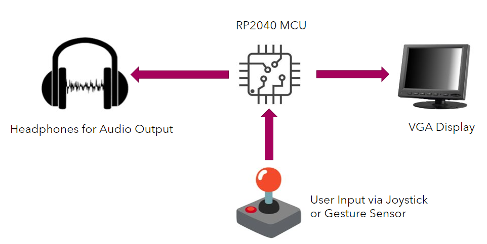
The PIO module on the RP2040 is quite a powerful peripheral, especially in terms of carrying out tasks that require precise timings and GPIO control. These tasks include handling communication protocols such as SPI, I2C, etc. In this project, we have utilized these capabilities of the PIO and the RP2040 as a whole to drive a 640x480 VGA display, and emulate the famous game - Piano Tiles integrated with spatial audio to provide an immersive experience. In the game, the user needs to intercept the falling tiles on the screen using a small base tile that is as the name suggests is present at the bottom of the screen. Each time a tile is intercepted a particular note is played. The spatial audio like effect is created based on which side the user intercepts the tile, i.e. if the tile is intercepted on the left side of the screen, the user will feel that the audio is coming from the left side and vice-versa for the right side. Headphones were used to implement this feature, driven using the PWM peripheral on the RP2040.
The repository containing the code is availabe on
GitHub can be accessed by clicking
here.
To get a little motivation for diving further into this, let's have a look at the end result.
For a detailed understanding of every component we will look at each of the features incorporated one by one.
First up is the VGA display. The VGA protocol works based on a few very precisely timed signals/pulses, which can be seen in the figure below.
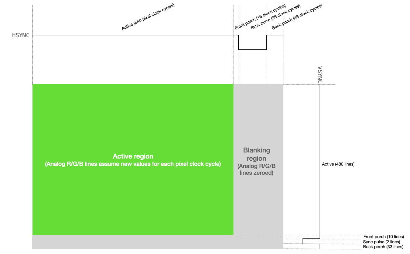
Here the HSYNC and VSYNC signals play a major role in terms of
communicating
with the display and deciding both the temporal and spatial placement of pixels. The former has
control
over when a new row of pixels should be displayed, and the latter controls when a new frame needs to
come
in. All of this is controlled by the PIO module on the RP2040, which runs at a clock speed of
25MHz.The whole
protocol can be explained in brief as follows:
HSYNC
signal as the name suggests (Horizontal Sync) needs to be high for 640 clock cycles.
HSYNC signal is active-high and starts out as HIGH. During this
time, the R, G and B pins are set to varying volatages
between 0 and 0.7V, in every clock cycle.
HSYNC enters into its front porch,
for
which it goes to a LOW state for 16 clock cycles. Similarly it then moves onto the
sync Pulse and back porch part of the protocol and behaves as shown in the
figure
above.
VSYNC (vertical sync) controls the frame.
So,
during the whole HSYNC operation, the VSYNC remains HIGH.
VSYNC signal also has the front porch, sync pulse, and the
back porch part to it, and behaves based on the diagram displayed above, i.e. it stays
at a HIGH state during its front porch for 10 lines (time needed for the
HSYNC signal to go through 10 rows), and so on.
The Josytick is a part of the user interface and enables the user to interact with the game. We used a dual-axis analog joystick for our game, that spit out values based on its current position. Since, we only needed a single DOF (Degree of freedom) for playing the game, we did not need data from both the axes of the joystick.
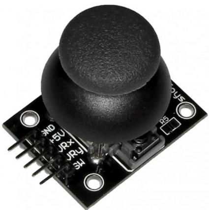
The joystick is connected with an onboard ADC on the RP2040, which converts the analog signal obtained from the joystick into discrete digital levels. Here, we have used a 12-bit value to represent the analog data. Hence, the values from the joystick had a range of 0 to 4095. Once we had the values from the ADC, with some testing we caliberated the joystick based on the requirement for the game. Then the data was mapped to a range of 0 to 50. Finally, after that based on that value the position of the joystick was determined.
Now we move on to the audio part of the game from the display.The RP2040 doesn't have a DAC onboard, so we tried to use the PWM peripheral to generate audio notes. This was possible by encoding the notes into a series of duty cycle values and storing it to an array, which can be accessed by the main code and played whenever a tile is intercepted. Also, note that using a single PWM cycle for each value in the array will not create a analog like sound effect, since we need some sort of persistence to emulate actual audio. Therefore, each value in the array is played for 8 cycles to emulate that persistence of sound. This will become more apparent and clear once we take a look at the code.
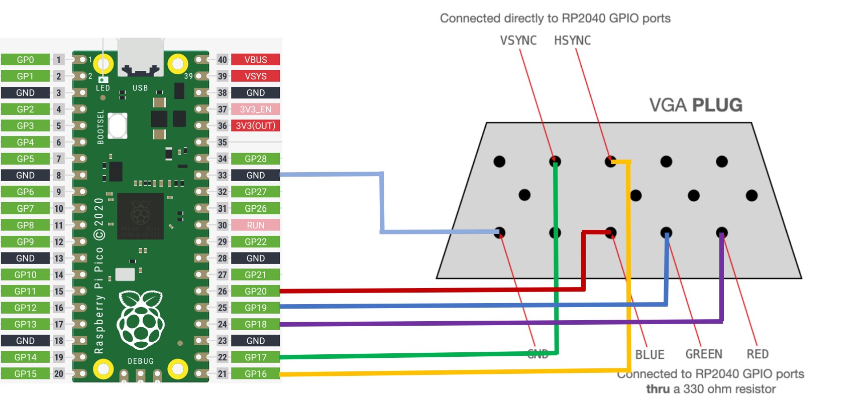
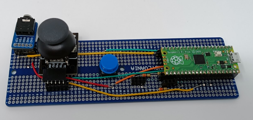
GPIO 16 pin of the microcontroller is connected to the HSYNC terminal
of
the VGA Plug.
GPIO 17 pin is connected to the VSYNC terminal.
GPIO 18 pin is connected to the VGA Red terminal of the Plug. A 330 Ω
resistor is attached in between to reduce the voltage going to the VGA plug.
GPIO 19 pin is connected to the VGA Green terminal via a 330 Ω
resistor.
GPIO 20 pin is connected to the VGA Blue terminal via a 330 Ω
resistor.
VGA GND terminal of the VGA plug is connected to the GND pin on the
microcontroller to provide necessary grounding.
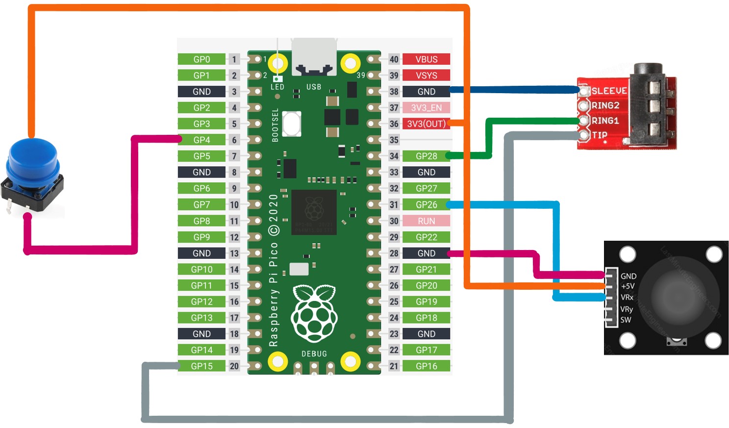
GPIO 28 pin of the Microcontroller is connected to the RNG terminal of
the
Audio Jack module. This terminal controls the Right side of the audio channel.
GPIO 15 pin is connected to the TIP terminal of the Audio Jack module.
This terminal controls the Left side of the audio channel.
GND pin is connected to the GND terminal of the module. This provides
grounding connection to the audio module.
GPIO 4 pin of the microcontroller.
3V3 pin, to provide
voltage to the restart pin based on user input.
GPIO 26 pin of the Raspberry Pi Pico is connected to the VRx terminal
of
the Joystick Module. This is responsible for controlling the joystick feedback in the horizontal (x)
axis.
3V3 pin of the microcontroller is connected to the 5V terminal of the
Joystick Module. This provides power to the module.
GND pin of the microcontroller is connected to the GND terminal of the
Joystick Module, which provides necessary grounding to the device.
Now let's take a look at the code that's driving our RP2040. Here also, we will split our code overview into smaller sections.
The following code snippet shows some of the standard as well as the hardware libraries that
we are going to use in our code. The hardware libraries included are a part of the
PICO-SDK
that abstract register access commands for that particular peripheral into functions and make them
available to the user. So, here we are using the adc, pio,
dma,
irq (interrupts) and the pwm peripheral. Finally, the
vga_graphics
library that we are using is created by Hunter
Adams,
which can be found here.
#include "vga_graphics.h"

#include <stdio.h>
#include <stdlib.h>
#include "pico/stdlib.h"
#include "pico/multicore.h"

#include "hardware/pio.h"
#include "hardware/dma.h"
#include "hardware/adc.h"
#include "registers.h"
#include "hardware/irq.h"  // interrupts

#include "hardware/pwm.h"  // pwm
#include "hardware/sync.h" // wait for interrupt
HSYNC
;
; Hunter Adams (vha3@cornell.edu)
; HSync generation for VGA driver


; Program name
.program hsync

; frontporch: 16 clocks (0.64us at 25MHz)
; sync pulse: 96 clocks (3.84us at 25MHz)
; back porch: 48 clocks (1.92us at 25MHz)
; active for: 640 clcks (25.6us at 25MHz)
;
; High for 704 cycles (28.16us at 25MHz)
; Low  for 96  cycles (3.84us at 25MHz)
; Total period of 800 cycles (32us at 25MHz)
;


pull block              ; Pull from FIFO to OSR (only happens once)
.wrap_target            ; Program wraps to here

; ACTIVE + FRONTPORCH
mov x, osr              ; Copy value from OSR to x scratch register
activeporch:
   jmp x-- activeporch  ; Remain high in active mode and front porch

; SYNC PULSE
pulse:
    set pins, 0 [31]    ; Low for hsync pulse (32 cycles)
    set pins, 0 [31]    ; Low for hsync pulse (64 cycles)
    set pins, 0 [31]    ; Low for hsync pulse (96 cycles)

; BACKPORCH
backporch:
    set pins, 1 [31]    ; High for back porch (32 cycles)
    set pins, 1 [12]    ; High for back porch (45 cycles)
    irq 0       [1]     ; Set IRQ to signal end of line (47 cycles)
.wrap


% c-sdk {
static inline void hsync_program_init(PIO pio, uint sm, uint offset, uint pin) {

    // creates state machine configuration object c, sets
    // to default configurations. I believe this function is auto-generated
    // and gets a name of <program name>_program_get_default_config
    // Yes, page 40 of SDK guide
    pio_sm_config c = hsync_program_get_default_config(offset);

    // Map the state machine's SET pin group to one pin, namely the `pin`
    // parameter to this function.
    sm_config_set_set_pins(&c, pin, 1);


    // Set clock division (div by 5 for 25 MHz state machine)
    sm_config_set_clkdiv(&c, 5) ;

    // Set this pin's GPIO function (connect PIO to the pad)
    pio_gpio_init(pio, pin);

    // pio_gpio_init(pio, pin+1);

    // Set the pin direction to output at the PIO
    pio_sm_set_consecutive_pindirs(pio, sm, pin, 1, true);

    // Load our configuration, and jump to the start of the program

    pio_sm_init(pio, sm, offset, &c);


    // Set the state machine running (commented out so can be synchronized w/ vsync)
    // pio_sm_set_enabled(pio, sm, true);
}
%}
VSYNC
;
; Hunter Adams (vha3@cornell.edu)
; VSync generation for VGA driver

; Program name
.program vsync
.side_set 1 opt

; frontporch: 10  lines
; sync pulse: 2   lines
; back porch: 33  lines (perhaps we try 32, since that's easier)
; active for: 480 lines
;
; Code size could be reduced with side setting


pull block                        ; Pull from FIFO to OSR (only once)
.wrap_target                      ; Program wraps to here

; ACTIVE
mov x, osr                        ; Copy value from OSR to x scratch register
activefront:
    wait 1 irq 0                  ; Wait for hsync to go high
    irq 1                         ; Signal that we're in active mode
    jmp x-- activefront           ; Remain in active mode, decrementing counter

; FRONTPORCH
set y, 9                          ;
frontporch:
    wait 1 irq 0                  ;
    jmp y-- frontporch            ;

; SYNC PULSE
set pins, 0                       ; Set pin low
wait 1 irq 0                      ; Wait for one line
wait 1 irq 0                      ; Wait for a second line

; BACKPORCH
set y, 31                         ; First part of back porch into y scratch register (and delays a cycle)
;set pins, 1                      ; Raise high for back porch (delaying a set cycle) - REPLACED WITH SIDESET
backporch:
    wait 1 irq 0   side 1         ; Wait for hsync to go high - SIDESET REPLACEMENT HERE
    jmp y-- backporch             ; Remain in backporch, decrementing counter

;wait 1 irq 0                      ; Wait for final (33rd) backporch line (eliminated)

.wrap                             ; Program wraps from here


% c-sdk {
static inline void vsync_program_init(PIO pio, uint sm, uint offset, uint pin) {

    // creates state machine configuration object c, sets
    // to default configurations. I believe this function is auto-generated
    // and gets a name of <program name>_program_get_default_config
    // Yes, page 40 of SDK guide
    pio_sm_config c = vsync_program_get_default_config(offset);

    // Map the state machine's SET pin group to one pin, namely the `pin`

    // parameter to this function.

    sm_config_set_set_pins(&c, pin, 1);
    sm_config_set_sideset_pins(&c, pin);

    // Set clock division (div by 5 for 25 MHz state machine)
    sm_config_set_clkdiv(&c, 5) ;

    // Set this pin's GPIO function (connect PIO to the pad)
    pio_gpio_init(pio, pin);
    // pio_gpio_init(pio, pin+1);


    // Set the pin direction to output at the PIO
    pio_sm_set_consecutive_pindirs(pio, sm, pin, 1, true);

    // Load our configuration, and jump to the start of the program
    pio_sm_init(pio, sm, offset, &c);

    // Set the state machine running (commented out so can be synchronized with hsync)
    // pio_sm_set_enabled(pio, sm, true);
}
%}
RGB
;
; Hunter Adams (vha3@cornell.edu)
; RGB generation for VGA driver

; Program name
.program rgb

pull block 					; Pull from FIFO to OSR (only once)
mov y, osr 					; Copy value from OSR to y scratch register
.wrap_target

set pins, 0 				; Zero RGB pins in blanking
mov x, y 					; Initialize counter variable

wait 1 irq 1 [3]			; Wait for vsync active mode (starts 5 cycles after execution)

colorout:
	pull block				; Pull color value
	out pins, 3	[4]			; Push out to pins (first pixel)
	out pins, 3	[2]			; Push out to pins (next pixel)
	jmp x-- colorout		; Stay here thru horizontal active mode

.wrap


% c-sdk {
static inline void rgb_program_init(PIO pio, uint sm, uint offset, uint pin) {

    // creates state machine configuration object c, sets
    // to default configurations. I believe this function is auto-generated
    // and gets a name of <program name>_program_get_default_config

    // Yes, page 40 of SDK guide
    pio_sm_config c = rgb_program_get_default_config(offset);

    // Map the state machine's SET and OUT pin group to three pins, the `pin`
    // parameter to this function is the lowest one. These groups overlap.
    sm_config_set_set_pins(&c, pin, 3);
    sm_config_set_out_pins(&c, pin, 3);

    // Set clock division (Commented out, this one runs at full speed)
    // sm_config_set_clkdiv(&c, 5) ;

    // Set this pin's GPIO function (connect PIO to the pad)
    pio_gpio_init(pio, pin);
    pio_gpio_init(pio, pin+1);
    pio_gpio_init(pio, pin+2);

    // Set the pin direction to output at the PIO (3 pins)
    pio_sm_set_consecutive_pindirs(pio, sm, pin, 3, true);

    // Load our configuration, and jump to the start of the program
    pio_sm_init(pio, sm, offset, &c);

    // Set the state machine running (commented out, I'll start this in the C)
    // pio_sm_set_enabled(pio, sm, true);
}
%}
Now, we define some macros and global variables that will be used by our code. As described earlier,
headphones are
used to emulate the spatial audio aspect of the game, and to achieve this we control the pins
connected to the
left and right channels of the headphones. Therefore, two macros named AUDIO_PIN_LEFT
and
AUDIO_PIN_RIGHT are created to improve the code readability and portability. Finally
there is another
macro named DELAY_CYCLES which controls the delay between the left and right audio
channel. As mentioned
above we encoded our audio notes into an array that contains the duty cycle information for creating
a PWM signal. This
array needs to be accessed by our main code to play the actual notes, so we placed the array into a
header file and included
that into the source file. Finally, the global variables namely wav_position,
flag_start,
audio_note_indx and interception_side are used by the interrupt service
routines, and the
function that each of them perform will be explained in later sections.
// Audio PIN is to match some of the design guide shields.
#define AUDIO_PIN_LEFT 28  // you can change this to whatever you like
#define AUDIO_PIN_RIGHT 15  // you can change this to whatever you like
#define DELAY_CYCLES 5

#include "audio_notes/A_major.h"
#include "audio_notes/E_major.h"
#include "audio_notes/B_major.h"
#include "audio_notes/Din_2.h"
#include "audio_notes/Tin_2.h"
#include "audio_notes/Na_2.h"
int wav_position = 0;
int flag_start = 0;
int audio_note_indx = 0;
int interception_side = 0;
Apart from this some macros are defined for determining the static (like the x coordinate of the
falling tiles in each column)
coordinates for the base tile and the tiles falling in each column. The macros
LEFT_VERT_TILES,
MID_VERT_TILES, and RIGHT_VERT_TILES are defined to configure the x
coordinate (the top-left vertex)
of the tile in the left, middle and the right side respectively.
// Define the co-ordinates for the Tiles and the Joystick controlled base.
#define LEFT_VERT 150
#define MID_VERT 290
#define RIGHT_VERT 430

#define LEFT_VERT_TILES 160
#define MID_VERT_TILES 300
#define RIGHT_VERT_TILES 440

#define RESTART_PIN 4
#define RESTART_PIN_REG ((volatile uint32_t *)(IO_BANK0_BASE + 0x010))
A restart button is integrated in the game to as the name suggests restart the game once
the game is over, i.e. a tile
is missed. This prevents the need to reset the microcontroller every time the game ends. To enable,
this operation a switch or
push button is connected to a GPIO pin on the RP2040, which is polled once the game is
over to determine when to
restart the game.
For controlling the left and right channels of the headphones, we have configured 2 separate
PWM
channels with interrupts. Following is the interrupt handler or the interrupt service routine for
the PWM
pin that is connected to the left channel of the headphone. This function defines the tasks that
need to be carried out
once a single PWM cycle completes, i.e. after one data element from the array that stores the audio
information is played.
Here we can see that the wav_position variable is used to index the data array that
contains our
audio note. Note that each data element in the array is played 8 times, to create a persistence
effect, because a simple
PWM signal is very "sharp" in a sense, and this gives us a sort of smoother effect. Hence, we right
shift the index by 3.
The WAV_DATA_LENGTH variable holds the length of the array, and therefore we left shift
it by 3. Keep in mind
that left shifting a number increases it and right shifting a number decreases it. The
PWM is a free-running
module and some sort of control is needed on the audio since we only want it to play once a tile is
intercepted. This is where the
flag_start variable comes into play, it determines whether an audio needs to be played
or not. If not the
GPIO pin connected to that channel is set to a LOW state. A brief
description of all the steps
this function performs is as follows:
flag_start variable is set indicating that an audio note needs
to be played.
audio_note_indx is used to determine which of the 3 notes needs to
be accessed currently. For
example we have used the NA, DIN and TIN notes and
0 is assigned to the
note NA, 1 is assigned to the note DIN and so on.
Some of these notes are generated using the Indian classicial musical instrument named
Tabla.
interception_side side variable. It has a value of 0 if the tile is
intercepted on the left side, a value of 1 if the tile is intercepted in the middle
and a value of 2 if the tile has been intercepted on the right (you get the idea).
To emulate spatial audio the side that the tile has been hit, needs to produce a louder
sound as compared to the opposite side, i.e. if the tile has been intercepted on the left, the
left
channel should have a higher amplitude as compared to the right channel. Similarly, in terms of
delay,
for the same example, the sound should reach the left channel first and then the right channel.
Therefore, for amplitude modulation, we add or subtract to the ON time present in
the array,
and for delay we manipulate the wav_position index such that the same audio note
played in
the left and right channel feels like it is shifted to the right in time.
else condition, when the flag_start variable is not
set,
as mentioned earlier we set the GPIO pin to 0 and increment our
audio_note_indx
variable untill the final note is reached, in which case it is reset to 0.
Similarly, the wav_position
is also set to 0 here. Note that the flag_start variable is unset to
enable that control over
when the audio notes are played.
void pwm_interrupt_handler() {

    pwm_clear_irq(pwm_gpio_to_slice_num(AUDIO_PIN_LEFT));

    if (wav_position < (WAV_DATA_LENGTH<<3) - 1 && flag_start == 1) {
        // set pwm level
        // allow the pwm value to repeat for 8 cycles this is >>3
        if (audio_note_indx == 0) {
            if (interception_side == 0 || interception_side == 1) {
                pwm_set_gpio_level(AUDIO_PIN_LEFT, WAV_DATA_NA[wav_position>>3]+20);
            } else {
                if (((wav_position>>3) - DELAY_CYCLES) <= 0) {
                    pwm_set_gpio_level(AUDIO_PIN_LEFT, 0);
                } else {
                    pwm_set_gpio_level(AUDIO_PIN_LEFT, WAV_DATA_NA[(wav_position>>3) - DELAY_CYCLES]-20);
                }
            }
        } else if (audio_note_indx == 1) {
            if (interception_side == 0 || interception_side == 1) {
                pwm_set_gpio_level(AUDIO_PIN_LEFT, WAV_DATA_DIN[wav_position>>3]+20);
            } else {
                if (((wav_position>>3) - DELAY_CYCLES) <= 0) {
                    pwm_set_gpio_level(AUDIO_PIN_LEFT, 0);
                } else {
                    pwm_set_gpio_level(AUDIO_PIN_LEFT, WAV_DATA_DIN[(wav_position>>3) - DELAY_CYCLES]-20);
                }
            }

        } else {
            if (interception_side == 0 || interception_side == 1) {
                pwm_set_gpio_level(AUDIO_PIN_LEFT, WAV_DATA_TIN[wav_position>>3]+20);
            } else {

                if (((wav_position>>3) - DELAY_CYCLES) <= 0) {
                    pwm_set_gpio_level(AUDIO_PIN_LEFT, 0);
                } else {
                    pwm_set_gpio_level(AUDIO_PIN_LEFT, WAV_DATA_TIN[(wav_position>>3) - DELAY_CYCLES]-20);
                }
            }
        }
        wav_position++;
    } else {
        // reset to start
        pwm_set_gpio_level(AUDIO_PIN_LEFT, 0);
        if (flag_start == 1) {
            wav_position = 0;
            flag_start = 0;
            if (audio_note_indx < 2) {
                audio_note_indx += 1;
            } else {
                audio_note_indx = 0;
            }
        }
    }
}
A very similar approach is taken for implementing the interrupt handler for the right channel of the headphone.
void pwm_interrupt_handler_2() {
    pwm_clear_irq(pwm_gpio_to_slice_num(AUDIO_PIN_RIGHT));
    if (wav_position < (WAV_DATA_LENGTH<<3) - 1 && flag_start == 1) {
        // set pwm level
        // allow the pwm value to repeat for 8 cycles this is >>3
        if (audio_note_indx == 0) {
            if (interception_side == 1 || interception_side == 2) {
                pwm_set_gpio_level(AUDIO_PIN_RIGHT, WAV_DATA_NA[wav_position>>3]);
            } else {
                if (((wav_position>>3) - DELAY_CYCLES) <= 0) {
                    pwm_set_gpio_level(AUDIO_PIN_RIGHT, 0);
                } else {
                    pwm_set_gpio_level(AUDIO_PIN_RIGHT, WAV_DATA_NA[(wav_position>>3) - DELAY_CYCLES]-80);
                }
            }
        } else if (audio_note_indx == 1) {
            if (interception_side == 1 || interception_side == 2) {
                pwm_set_gpio_level(AUDIO_PIN_RIGHT, WAV_DATA_DIN[wav_position>>3]);
            } else {
                if (((wav_position>>3) - DELAY_CYCLES) <= 0) {
                    pwm_set_gpio_level(AUDIO_PIN_RIGHT, 0);
                } else {
                    pwm_set_gpio_level(AUDIO_PIN_RIGHT, WAV_DATA_DIN[(wav_position>>3) - DELAY_CYCLES]-80);
                }
            }
        } else {
            if (interception_side == 1 || interception_side == 2) {
                pwm_set_gpio_level(AUDIO_PIN_RIGHT, WAV_DATA_TIN[wav_position>>3]);

            } else {
                if (((wav_position>>3) - DELAY_CYCLES) <= 0) {
                    pwm_set_gpio_level(AUDIO_PIN_RIGHT, 0);
                } else {
                    pwm_set_gpio_level(AUDIO_PIN_RIGHT, WAV_DATA_TIN[(wav_position>>3) - DELAY_CYCLES]-80);
                }
            }
        }
        wav_position++;
    } else {
        // reset to start
        pwm_set_gpio_level(AUDIO_PIN_RIGHT, 0);
        if (flag_start == 1) {
            wav_position = 0;

            flag_start = 0;
            if (audio_note_indx < 2) {
                audio_note_indx += 1;
            } else {
                audio_note_indx = 0;
            }
        }
    }
}
Now, let's move onto implementing the base tile, i.e. user interaction functionality. Here, we need
to move the base
tile based on the current position of the joystick. To do this, firstly the raw adc
value needs to be
read from the GPIO pin. We have used ADC0, so the function
adc_select_input(0)
will select the adc for us. The raw value read from the adc is stored in a
variable named
adc_x_raw and this value is used to calliberate the joystick. A range of values is used
in this process
for thresholding and reducing the de-bouncing effect. A 12-bit ADC is used
to discretize the raw values obtained from the joystick. Once the calliberation is done, the
resulting value is mapped
to a range of 0 to 100, and based on this value thresholding is done once again to determine where
the base tile needs
to be positioned. The fillRect function is a part of the vga_graphics
library that enables us
to draw a filled rectangle on the screen. This is done by using two for loops, and
calling the
drawPixel function in each iteration, which in-turn populates or updates the
VGA_DATA_ARRAY
based on the color and position of the pixel. Therefore, at the fillRect level, it
requires the top-left
vertex of the rectangle that needs to be drawn as its arguments, along with the width and height of
the rectangle and
finally the color that the rectangle needs to be filled with. At the end, we sleep for some time and
return the
adc_x variable. This will be required for determining the side on which the tile was
intercepted or where
the base tile is in reference to the current state of the screen.
uint act_adc() {
    adc_select_input(0);
    uint adc_x_raw = adc_read();
    uint adc_x = 0;

    if (adc_x_raw > 1600 && adc_x_raw < 2400) {
        adc_x = 2048;
    } else {
        adc_x = adc_x_raw;
    }

    adc_x = (adc_x * 100) / 4095;

    printf("%d, %d\n", adc_x, adc_x_raw);

    if (adc_x == 50){
        fillRect(MID_VERT,460,60,20,WHITE);
        fillRect(LEFT_VERT,460,60,20,0);
        fillRect(RIGHT_VERT,460,60,20,0);
    }
    else if (adc_x > 50) {
        fillRect(RIGHT_VERT,460,60,20,WHITE);
        fillRect(LEFT_VERT,460,60,20,0);
        fillRect(MID_VERT,460,60,20,0);
    }else if (adc_x < 50) {
        fillRect(LEFT_VERT,460,60,20,WHITE);
        fillRect(MID_VERT,460,60,20,0);
        fillRect(RIGHT_VERT,460,60,20,0);
    }
    sleep_ms(10);
    return adc_x;
}
For a immersive and enjoyable experience the game animation needs to be engaging, lag-free and
smooth. This task of making
the tiles fall was repetitive in the sense that every tile needed to have this animation, hence we
created a helper function that
would avoid code repetition and improve readability. The draw_fill_rect function takes
in an arguments the
parameters required for the fillRect function, and another argument named
inc_dec. As explained above
the fillRect function draws rectangles on the screen, which now need to be animated.
Hence, to do this, we
first thought of erasing the whole drawn rectangle and creating another one at a position lower than
its last position to
give an impression that the tile is falling. However, this did not pan out well, it lead to choppy
animation since erasing
the whole rectangle was taking up quite a bit of time. Therefore, we decided to erase a small
rectangle from the top of the
tile and create another at the bottom of the tile, to emulate a falling tile. So, now every time the
tile needs to descend
a small part of it is erased from the top and a similar portion is created at the bottom. This is
where the inc_dec
parameter comes into play, it decides the height of the small portion that is going to be erased at
the top and created at the
bottom.
// Helper function to abstract the animation.
void draw_fill_rect(short x, short y, short w, short h, char color, short inc_dec){
    fillRect(x,y,w,h,color);
    fillRect(x,y,w,inc_dec,0);
    fillRect(x,y+h,w,inc_dec,color);
    sleep_ms(10);
}
The score needs to be updated every time a tile is intercepted, to do this, firstly the entire area
that shows the score is
erased. For displaying score we need digits, which are passed as characters to the
drawChar function. We decided
to have a maximum of 3 digits to represent the score, and hence created a character array of size 3
that stores each digit of
the current score which is passed as a parameter to the update_score function. Each
digit is extracted from the
current score using the % operation with 10, and each digit becomes an
element in the character array.
Then the drawChar function is called thrice to draw each digit on the screen.
// Helper function to keep track of the user's score.
void update_score(uint score){
    fillRect(30,60,240,20,0);
    /* setCursor(30, 30); */
    /* setTextSize(3); */
    char str_score[3] = {'0', '0', '0'};
    str_score[2] = (score % 10) + '0';
    str_score[1] = ((score/10) % 10) + '0';
    str_score[0] = (((score/10)/10) % 10) + '0';
    drawChar(30, 60, str_score[0], WHITE, 0, 2);
    drawChar(45, 60, str_score[1], WHITE, 0, 2);
    drawChar(60, 60, str_score[2], WHITE, 0, 2);
}
main
Function
Let's take a look at configuring the PWM channels for the audio generation. The
GPIO pins need to
be mapped to the PWM function. After that the interrupts are configured to fire when a
single PWM
cycle is complete, which is determined by the PWM_IRQ_WRAP macro. Once that is done,
each channel is assigned
an interrupt service routine. Finally, we get the default PWM config struct and update
the clkdiv and
wrap values. The latter is set to 250 which means that the counter will go
upto 250 and
then return to 0. At the end, both the GPIO pins are set to a
LOW state.
int main() {

    /////////////////////////////////// AUDIO CODE //////////////////////////////////////////
    gpio_set_function(AUDIO_PIN_LEFT, GPIO_FUNC_PWM);
    gpio_set_function(AUDIO_PIN_RIGHT, GPIO_FUNC_PWM);

    int audio_pin_slice = pwm_gpio_to_slice_num(AUDIO_PIN_LEFT);
    int audio_pin_slice_2 = pwm_gpio_to_slice_num(AUDIO_PIN_RIGHT);


    // Setup PWM interrupt to fire when PWM cycle is complete
    pwm_clear_irq(audio_pin_slice);
    pwm_clear_irq(audio_pin_slice_2);
    pwm_set_irq_mask_enabled((1u<<6) | (1u<<7), true);

    // set the handle function above
    irq_add_shared_handler(PWM_IRQ_WRAP, pwm_interrupt_handler, 0);
    irq_add_shared_handler(PWM_IRQ_WRAP, pwm_interrupt_handler_2, 1);
    irq_set_enabled(PWM_IRQ_WRAP, true);

    // Setup PWM for audio output
    pwm_config config = pwm_get_default_config();

    /* Base clock 176,000,000 Hz divide by wrap 250 then the clock divider further divides
     * to set the interrupt rate.
     *
     * 11 KHz is fine for speech. Phone lines generally sample at 8 KHz
     *
     *
     * So clkdiv should be as follows for given sample rate
     *  8.0f for 11 KHz
     *  4.0f for 22 KHz
     *  2.0f for 44 KHz etc
     */
    pwm_config_set_clkdiv(&config, 8.0f);
    pwm_config_set_wrap(&config, 250);
    pwm_init(audio_pin_slice, &config, true);

    pwm_init(audio_pin_slice_2, &config, true);


    pwm_set_gpio_level(AUDIO_PIN_LEFT, 0);
    pwm_set_gpio_level(AUDIO_PIN_RIGHT, 0);
    /////////////////////////////////// AUDIO CODE //////////////////////////////////////////
Now we will move onto the configuration of the RESTART_PIN and the joystick. For the
former we first initialize the GPIO pin
connected the restart button, and then set it to input mode. After that, stdio
and the VGA library is initialized. For
the joystick, the adc peripheral is initialized. Then the GPIO pin is
mapped to the adc. Finally some variables
are defined which will keep track of our tiles' positions, the current score, the current joystick
position, etc. At the end we initialize the score board
and call the update_score function.
    gpio_init(RESTART_PIN);
    gpio_set_dir(RESTART_PIN, GPIO_IN);

    // Initialize stdio
    stdio_init_all();

    // Initialize VGA
    initVGA();

    adc_init();


    // Make sure GPIO is high-impedance, no pullups etc
    adc_gpio_init(26);

    // Initialize indices for the tiles, the score for the user, and the restart button status.
    uint blue_indx = 20, green_indx = 40, cyan_indx = 60, joystick_pos = 0;
    uint curr_score = 0, buttons_status = 0;

    drawChar(30, 30, 'S', WHITE, 0, 2);
    drawChar(45, 30, 'c', WHITE, 0, 2);

    drawChar(60, 30, 'o', WHITE, 0, 2);
    drawChar(75, 30, 'r', WHITE, 0, 2);

    drawChar(90, 30, 'e', WHITE, 0, 2);
    drawChar(105, 30, ':', WHITE, 0, 2);
    update_score(curr_score);

    // Sleep for some time, to give the user a chance to get READY.
    sleep_ms(5000);
For the actual game play, we use 2 while loops, where the former controls the game
status, and the latter controls and animates the falling tiles.
Once the user misses a tile, the code exits from the inner while loop and polls the
restart button, once the button is pressed the game re-initializes.
For animation the y-cordinate of the tiles is incremented in multiples of
4, this multiplicative factor can be adjusted based on the
speed requirement, i.e. the speed at which the tiles should fall. Therefore, the higher the
multiplicative factor the faster the tiles fall. The y-cordinate
also helps us determine whether the tile has reached the bottom of the screen. Now, based on the
current joystick position and the state of the screen the
current_score, flag_start, and the interception_side
variables are updated. Every time a tile is hit, it blinks with red color
and then disappears. Finally, when a tile is missed the drawChar function is used to
display "Game Over!!" on the screen and the tiles are cleared. After that
the game waits for the restart button to be pressed. This complete process repeats indefinitely.
    while(true) {
        while (true){
            // Get the current joystick position.
            joystick_pos = act_adc();

            // Check if the cyan colored tile, reached the bottom of the screen. If so
            // reset it's co-ordinates back to the top, and check if it was intercepted,
            // if it was change the tile's color to RED, and make it blink twice, suggesting
            // that the tile was intercepted, and update the user's score. If the tile was missed,
            // exit the loop.
            if (cyan_indx > 89) {
                cyan_indx = 0;
                fillRect(RIGHT_VERT_TILES,360,40,100,0);
                if (joystick_pos > 50) {
                    sleep_ms(40);
                    fillRect(RIGHT_VERT_TILES,360,40,100,RED);
                    sleep_ms(40);
                    fillRect(RIGHT_VERT_TILES,360,40,100,0);
                    curr_score += 1;
                    update_score(curr_score);
                    flag_start = 1;
                    interception_side = 2;
                    __wfi();
                } else {
                    fillRect(RIGHT_VERT,460,60,20,0);
                    break;
                }
            }


            // Check if the green colored tile, reached the bottom of the screen. If so
            // reset it's co-ordinates back to the top, and check if it was intercepted,
            // if it was change the tile's color to RED, and make it blink twice, suggesting
            // that the tile was intercepted, and update the user's score. If the tile was missed,
            // exit the loop.
            if (green_indx > 89) {
                green_indx = 0;
                fillRect(MID_VERT_TILES,360,40,100,0);

                if (joystick_pos == 50) {
                    sleep_ms(40);
                    fillRect(MID_VERT_TILES,360,40,100,RED);
                    sleep_ms(40);
                    fillRect(MID_VERT_TILES,360,40,100,0);
                    curr_score += 1;
                    update_score(curr_score);
                    flag_start = 1;
                    interception_side = 1;
                    __wfi();
                } else {
                    fillRect(MID_VERT,460,60,20,0);
                    break;
                }
            }

            // Check if the blue colored tile, reached the bottom of the screen. If so
            // reset it's co-ordinates back to the top, and check if it was intercepted,
            // if it was change the tile's color to RED, and make it blink twice, suggesting
            // that the tile was intercepted, and update the user's score. If the tile was missed,
            // exit the loop.
            if (blue_indx > 89) {
                blue_indx = 0;
                fillRect(LEFT_VERT_TILES,360,40,100,0);
                if (joystick_pos < 50) {
                    sleep_ms(40);
                    fillRect(LEFT_VERT_TILES,360,40,100,RED);
                    sleep_ms(40);
                    fillRect(LEFT_VERT_TILES,360,40,100,0);
                    curr_score += 1;
                    update_score(curr_score);
                    flag_start = 1;
                    interception_side = 0;
                    __wfi();
                } else {
                    fillRect(LEFT_VERT,460,60,20,0);
                    break;
                }
            }

            // Animate the tiles, by erasing a small rectangle of dimensions 4x40 from it's
            // top and creating a rectangle at the bottom with the exact same dimensions. This
            // emulates the falling tiles.
            draw_fill_rect(LEFT_VERT_TILES,(blue_indx*4),40,100,BLUE,4);
            draw_fill_rect(MID_VERT_TILES,(green_indx*4),40,100,GREEN,4);
            draw_fill_rect(RIGHT_VERT_TILES,(cyan_indx*4),40,100,CYAN,4);

            // Update the co-ordinates for each of the tile.
            cyan_indx++;
            green_indx++;
            blue_indx++;
        }
        // Erase the tiles, to clear the screen.

        fillRect(LEFT_VERT_TILES,(blue_indx*4),40,100,0);
        fillRect(MID_VERT_TILES,(green_indx*4),40,100,0);
        fillRect(RIGHT_VERT_TILES,(cyan_indx*4),40,100,0);

        // Display Game over.
        drawChar(180, 240, 'G', WHITE, 0, 5);
        drawChar(210, 240, 'A', WHITE, 0, 5);
        drawChar(240, 240, 'M', WHITE, 0, 5);
        drawChar(270, 240, 'E', WHITE, 0, 5);
        drawChar(300, 240, ' ', WHITE, 0, 5);
        drawChar(330, 240, 'O', WHITE, 0, 5);
        drawChar(360, 240, 'V', WHITE, 0, 5);
        drawChar(390, 240, 'E', WHITE, 0, 5);
        drawChar(420, 240, 'R', WHITE, 0, 5);
        drawChar(450, 240, '!', WHITE, 0, 5);

        drawChar(480, 240, '!', WHITE, 0, 5);

        // Wait here untill restart button is pressed.
        buttons_status = register_read(RESTART_PIN_REG);
        printf("0x%08x\n", buttons_status);
        while (buttons_status == 0){
            buttons_status = register_read(RESTART_PIN_REG);
            /* printf("0x%08x\n", buttons_status); */
            sleep_ms(10);
        }

        // Clear the screen, and reset the score.
        fillRect(180,240,400,100,0);
        curr_score = 0;
        update_score(curr_score);

        }
    return 0;
}
First off , we tried implementing an animation of a single tile using the fillRect
function which was defined in the vga_graphics library. This function uses the
drawPixel function. The fillRect uses the coordinates of the top left vertex
of the rectangle to do so. We began by trying to draw a single rectangle and getting it to move
horizontally. We did this by drawing a rectangle and then erasing it. We then drew another rectangle by
setting the top left vertex coordinate as the coordinate of the top right vertex of the previous
rectangle that we just erased . We repeated this process along the entire X axis to make it look like
that the tile was moving horizontally across the X axis. Once we were able to do this , we tried to
implement the tiles moving top to down since that was the use case for our project.
Once we were able to replicate a pattern of a falling tile , we did this for 3 columns since we have implemented 3 columns in our game. We then had to create our base tile at the bottom of the screen that we would use to intercept the falling tiles. Once we had the base tile and the falling tiles aspect of the game set up exactly how we wanted , we implemented a score tracker that would keep incrementing as and when you intercept tiles and would end the game if you miss a certain tile.
We then tried to find ways of implementing spatial audio where a more prominent sound would be played on
the left or the right channel of the headphone depending on the side of the screen that the tile had
been intercepted. Since the RP2040 does not have a Digital to Analog converter, we tried using the PWM
peripheral to produce audio notes. We referred to a piece of code that takes .wav files as
input and converts it into PWM data. Initially , we played around with the amplitudes of the audio notes
to bring spatial audio in effect , however , the difference in audio levels was not very significant. To
overcome this , we then implemented delays on top of amplitude reduction to bring about a perciptible
difference in the right and left channels of the headphone.
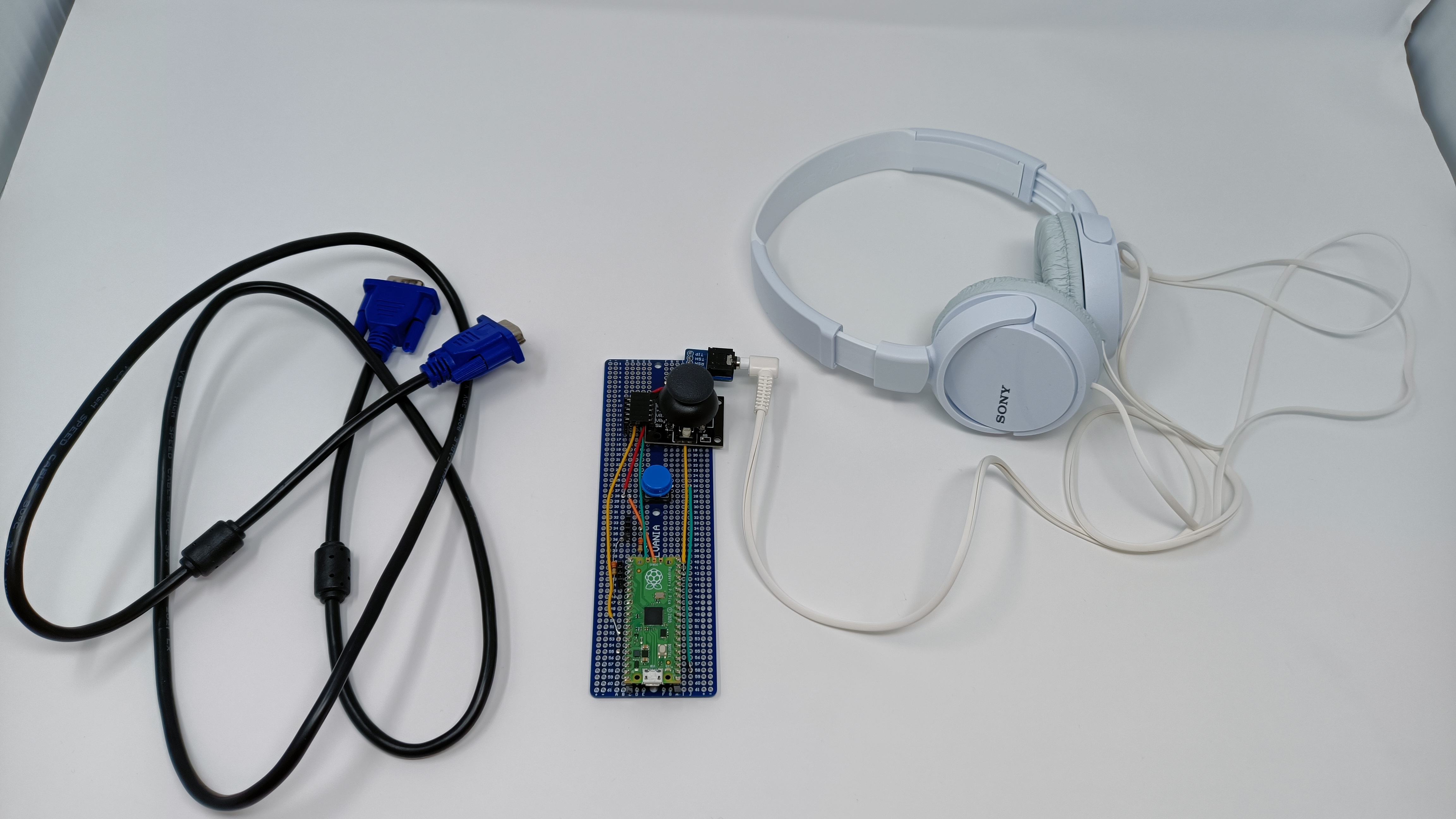
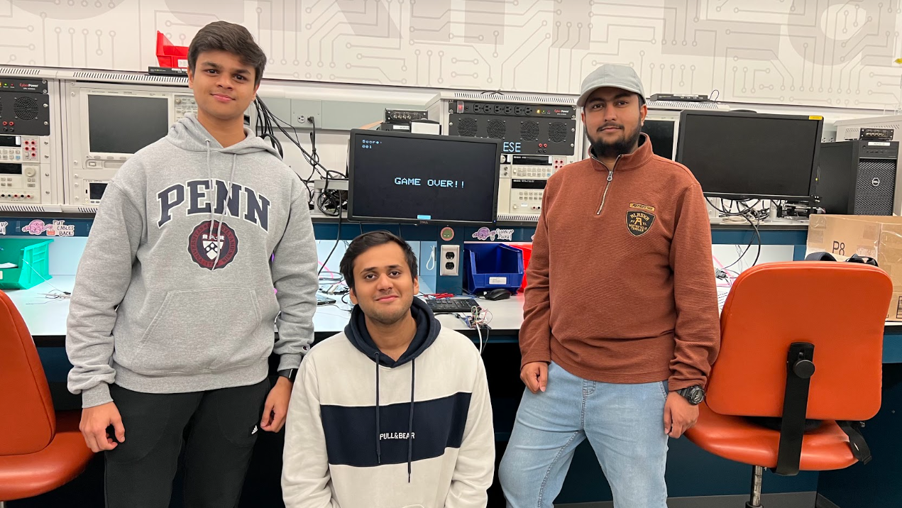
These pictures and videos demonstrate the working of our project. We learnt a lot during the course, and were able to get a hands-on experience with microcontrollers and various communication protocols.